Mobile Mapping vs. SLAM: A Difference in Technology
News |
Nov 18, 2026
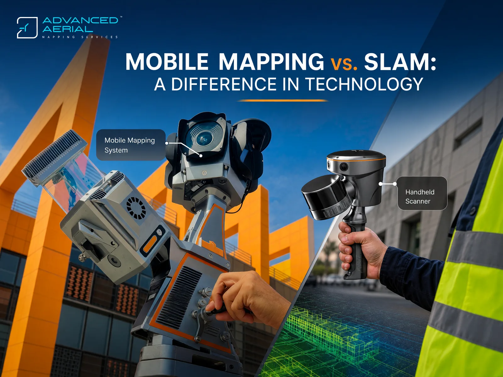
Vehicle-based mobile mapping and SLAM both capture 3D point clouds and imagery, but they work out their position in different ways. That difference decides where each one performs best.
Recently, we invested in several SLAM sensors, the CHCNAV RS10, even though we already operate an established vehicle-based mobile mapping system, the CHCNAV AlphaUni 20 (AU20), with a 360-degree camera installed. We have been asked why we added SLAM with 360-degree capture and what the need was. This article answers that by comparing the two technologies and the two systems.
The short answer is that they are not competitors. Each solves a different positioning problem, and each works well where the other struggles.
HOW EACH SYSTEM KNOWS WHERE IT IS
Vehicle-based mobile mapping is built on a trajectory. A GNSS receiver (Global Navigation Satellite System, which includes GPS, GLONASS, Galileo and BeiDou) gives absolute position. An inertial measurement unit (IMU) records the vehicle's orientation and motion, and an odometer records distance traveled.
Post-processing combines these into one accurate path. The LiDAR and camera data are then georeferenced along that path, so the point cloud lands directly in a real-world coordinate system.
The weak point is the sky. Under bridges, in tunnels or between tall buildings, GNSS signals degrade. The IMU can bridge short outages, but errors grow the longer the signal is lost. Control points and careful processing limit this, but they do not remove it.
SLAM (Simultaneous Localization and Mapping) needs no satellites. The sensor compares each new LiDAR scan with the ones before it, usually with IMU support. As it moves, it builds a map and estimates its own path through that map at the same time. This lets it work where GNSS cannot: inside buildings, in tunnels and underground spaces, and under dense canopy.
The trade-off is that a pure SLAM position is relative to where the scan began. Small errors, known as drift, can accumulate over long distances. Loop closure, which means returning to a previously mapped point so the software can correct the path, reduces drift. Surveyed control points tie the result to a coordinate system. Hybrid units that add a GNSS RTK receiver, such as the RS10 described below, reduce this limitation wherever satellite signal is available.
OUR SYSTEMS AT A GLANCE
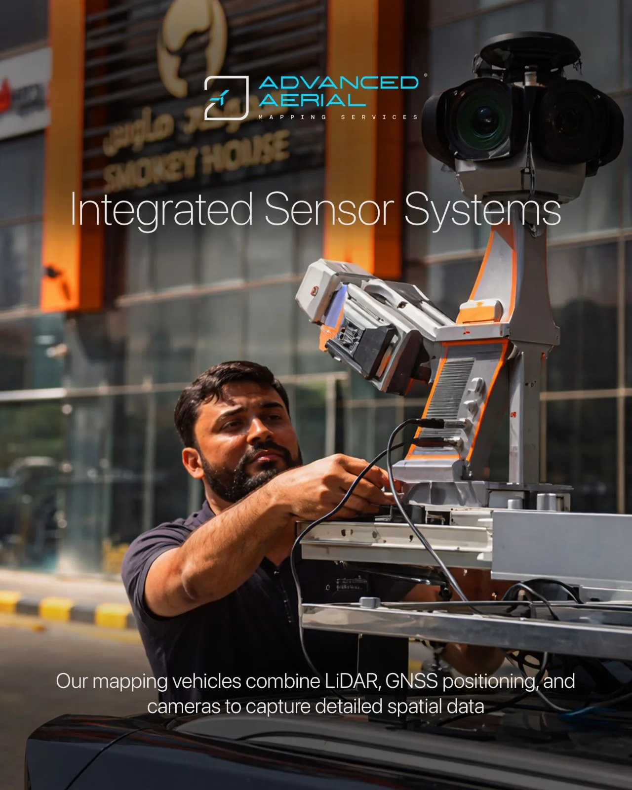
Figure 1. The AAMS vehicle-based CHCNAV AU20 mounted on the AAMS survey vehicle
CHCNAV AU20: vehicle-based LiDAR mobile mapping
The AU20 is a multi-platform LiDAR mobile mapping system. It can be integrated into land vehicles such as cars, boats and trains, and it can also be mounted on a backpack for narrow areas. We use it on road corridors and large areas that a vehicle can reach.
Key specifications (manufacturer figures):
- Point rate: up to 2,000,000 points per second.
- Accuracy: 5 mm repeated range accuracy and an absolute accuracy of 2 to 5 cm, even in challenging environments.
- Vegetation: multi-target capability of up to 16 echoes, which helps the laser reach the ground through foliage.
- Setup: switching to vehicle mode takes about five minutes, regardless of car type.
- Imagery: LiDAR data is combined with panoramic imagery.
Benefits for clients:
- Fast, continuous capture of long road corridors and highways
- Dense point clouds with panoramic imagery for design, inspection and asset inventories
- Better ground detail under vegetation
- One sensor that can be reconfigured for other platforms
CHCNAV RS10: handheld SLAM with GNSS RTK
The RS10 brings GNSS RTK, laser scanning and visual SLAM together in one handheld platform. RTK (real-time kinematic) is a GNSS technique that gives centimeter-level positions when satellite signal is good. Our units are the 32-channel version.
Key specifications (manufacturer figures):
- LiDAR: 32 channels with a range of up to 300 m.
- Accuracy: absolute accuracy of up to 5 cm and relative accuracy better than 1 cm.
- Weak or no GNSS: when the signal is weak or absent, coordinates are calculated from LiDAR and visual SLAM data.
- Weight: 1.9 kg including the RTK unit and battery.
- Battery: 60 minutes per battery, hot-swappable without powering off.
Benefits for clients:
- Seamless capture from outdoors to indoors and underground, in one pass
- Access to places a vehicle cannot enter, such as narrow streets, building interiors and car parks
- RTK constrains the SLAM trajectory, so the operator does not need to walk loop closures to keep data aligned
- Fast capture on foot with one operator
Quoted figures come from the manufacturer. Achieved accuracy depends on the environment, GNSS conditions and control, so we confirm it per project.
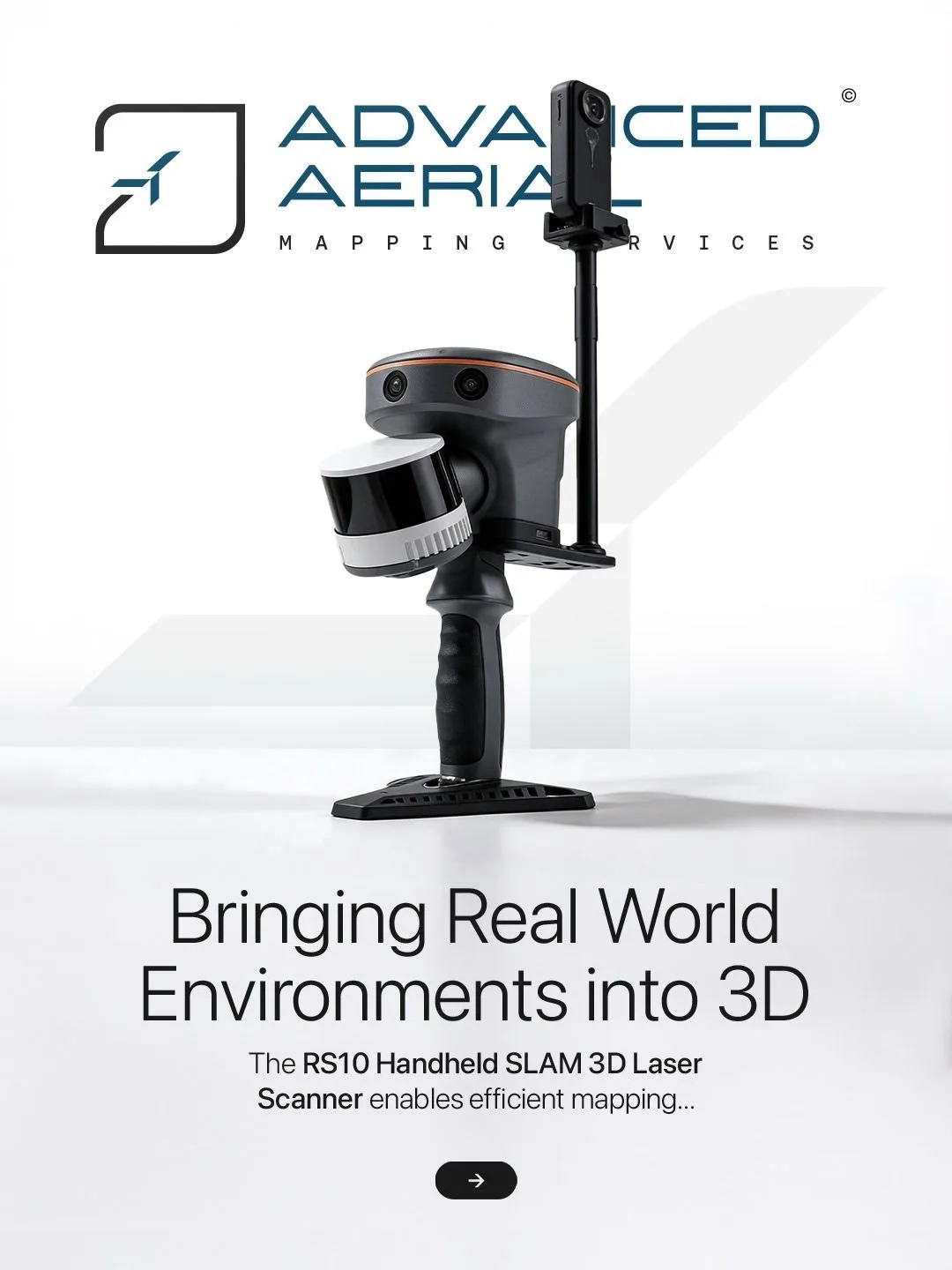
Figure 2. The AAMS CHCNAV RS10 – Handheld Scanner
SIDE BY SIDE
Positioning
- Vehicle-based mobile mapping (AU20): GNSS + IMU + odometer, post-processed
- SLAM (RS10 and similar): Scan matching and visual SLAM, with RTK where available
Reference frame
- Vehicle-based mobile mapping (AU20): Absolute, from GNSS and base station data
- SLAM (RS10 and similar): Relative in GNSS-denied areas; absolute where RTK is available
Best environment
- Vehicle-based mobile mapping (AU20): Roads, highways and open to semi-open corridors
- SLAM (RS10 and similar): Interiors, tunnels, underground, dense vegetation, narrow or pedestrian-only areas
Coverage
- Vehicle-based mobile mapping (AU20): Long road networks captured from a moving vehicle
- SLAM (RS10 and similar): Detailed capture on foot, over shorter distances
Main limitation
- Vehicle-based mobile mapping (AU20): GNSS degradation; needs vehicle access
- SLAM (RS10 and similar): Drift over distance in GNSS-denied areas; control needed for absolute accuracy
Typical outputs
- Vehicle-based mobile mapping (AU20): Point cloud, 360° imagery
- SLAM (RS10 and similar): Point cloud, 360° imagery
WHY SLAM WITH A 360-DEGREE CAMERA
Our vehicle system already delivers a point cloud and 360-degree imagery together. Clients use that combination to measure, inspect and document assets from the office. SLAM with a 360-degree camera brings the same kind of deliverable to places the vehicle cannot enter.
- Continuity of data. A project can have one consistent product, point cloud plus panoramic imagery, whether the area is a highway or the inside of a building.
- Colorized point clouds. The camera data colors the points, which makes features easier to identify.
- Visual record. Panoramic images document site conditions, support asset inspection and allow remote review.
- Simple capture. A 360-degree camera records in all directions, so the operator does not need to aim it while walking.
USING BOTH ON ONE PROJECT
On a typical project, the AU20 captures the main road network or corridor quickly and with absolute positioning. The RS10 then captures what the vehicle cannot reach, such as underpasses, tunnels, covered structures, building interiors or narrow access routes. Shared control points and overlapping areas let the two datasets be aligned into one model.
WHAT DO YOU ACTUALLY GET FROM SLAM?
Simultaneous Localisation and Mapping (SLAM) enables a mobile system to determine its position and orientation while simultaneously building a representation of its surrounding environment.
The primary outputs of SLAM are:
- Real-Time Position and Trajectory: Continuous estimates of the sensor's position (X, Y, Z) and orientation (roll, pitch, yaw) as it moves through an environment.
- Relative 3D Environmental Map: A locally constructed representation of the surrounding environment, which may include point clouds, voxel maps, or occupancy grids. This allows the system to understand its position relative to surrounding objects and spatial features.
- Loop-Closure Corrections: When the system recognises a previously visited location, SLAM algorithms can use this information to correct accumulated positional and mapping errors, improving overall consistency.
- Localisation Without Continuous GNSS: SLAM can maintain positioning and mapping capabilities in environments where satellite signals are weak or unavailable, including indoor spaces, tunnels, and urban canyons.
Important Consideration: Standalone SLAM generally produces a locally referenced map rather than inherently providing absolute geospatial coordinates. Without external georeferencing, such as GNSS/INS integration, surveyed control points, or other positioning references, positional drift can accumulate, particularly along long routes or in geometrically repetitive and feature-poor environments.
WHAT DO YOU ACTUALLY GET FROM MOBILE MAPPING?
Mobile Mapping is a broader geospatial data acquisition approach that combines positioning technologies, laser scanning, imaging systems, and other sensors mounted on a moving platform, such as a vehicle, backpack, or handheld unit.
Its primary outputs include:
- High-Density 3D Point Clouds: Millions or billions of spatially referenced points capturing the geometry of roads, terrain, buildings, facades, utilities, and other infrastructure assets.
- High-Resolution Panoramic Imagery: Georeferenced 360-degree imagery, and where supported, additional forward-facing or nadir imagery, synchronised with the spatial dataset to provide visual context.
- Georeferenced Spatial Data: Data positioned within a defined coordinate reference system and, where required, tied to a recognised geodetic datum through GNSS/INS positioning, RTK/PPK corrections, and surveyed ground control.
- Infrastructure and Asset Mapping: Detailed spatial information that supports road inventories, utility mapping, asset management, engineering surveys, corridor mapping, and GIS integration.
- Integrated Multi-Sensor Data: Depending on the system configuration, LiDAR, cameras, GNSS, IMU, and other sensors work together to produce comprehensive and spatially consistent datasets.
WHERE SLAM AND MOBILE MAPPING COME TOGETHER
The two technologies are not necessarily competing solutions. In modern geospatial workflows, they complement each other.
When SLAM is integrated into a Mobile Mapping System, it provides an additional localisation capability, particularly where conventional GNSS positioning becomes unreliable or unavailable.
For example:
- Urban Environments: Helps maintain trajectory estimation between tall buildings where satellite visibility is obstructed.
- Underground Infrastructure: Supports mapping inside tunnels, basements, and underground utility environments.
- Indoor Mapping: Enables continuous spatial data acquisition where GNSS signals are unavailable.
- Complex Infrastructure: Helps maintain mapping continuity around structures, enclosed spaces, and areas with challenging positioning conditions.
By combining SLAM with GNSS/INS, LiDAR, imaging, and appropriate survey control, a mobile mapping workflow can achieve more robust positioning and deliver detailed, georeferenced 3D datasets.
The Key Distinction: SLAM is fundamentally a localisation and mapping methodology, whereas Mobile Mapping is a complete data acquisition and geospatial mapping workflow. SLAM can be one of the technologies powering a Mobile Mapping System.
CHOOSING THE RIGHT TECHNOLOGY
- Choose vehicle-based mobile mapping when the area is reachable by road, the sky is largely open and long distances must be covered with absolute accuracy.
- Choose SLAM when GNSS is unreliable or unavailable, vehicle access is impossible, or close-range detail is the priority.
- Use both when a project crosses open and enclosed environments and needs a single, continuous dataset.
Not sure which approach suits your site? Talk to the AAMS team about mobile mapping and SLAM scanning at www.aams-sa.com.
CONCLUSION
In one line: vehicle-based mobile mapping covers long, open corridors with absolute accuracy, while SLAM captures detailed data where vehicles and satellites cannot reach.
Partner with AAMS for Smarter Geospatial Solutions
At Advanced Aerial Mapping Services (AAMS), we combine advanced surveying technologies, experienced geospatial professionals, and integrated data acquisition capabilities to deliver accurate, reliable, and actionable spatial intelligence.
With our headquarters in Saudi Arabia and offices in the UK and South Africa, AAMS provides comprehensive geospatial solutions, including SLAM-based mobile mapping, terrestrial and mobile LiDAR scanning, aerial surveys, photogrammetry, and 3D reality capture.
By integrating advanced technologies such as CHCNAV SLAM scanners, LiDAR systems, GNSS/INS positioning, and high-resolution imaging, we help clients capture complex environments, overcome challenging surveying conditions, and transform raw spatial data into valuable geospatial intelligence.
Looking to enhance your next surveying or mapping project?
Connect with AAMS to discover how our integrated mobile mapping and geospatial solutions can support smarter decisions, better asset management, and more informed infrastructure development.
Related News
all News